Two or more chillers are piped in series counterflow SCF when the following conditions are met Figure 2. Centrifugal chiller will be chosen andor sized accordingly ie.

Improving System Efficiency Using Series Counterflow Piping Strategy 2021 01 14 Process Cooling
It may be tempting to select two centrifugal.

. The heat reclaim chiller s low source protection feature will ensure that chilled water is provided at a tem. In a SCF configuration. Water flows through the condenser in series D E F Figure 2 c.
Now that second chiller with the 45 exiting to the space has condenser water from the cooling tower entering in at 85 and rising to. Ad Everyday Low Prices on an Amazing Selection. Optimized Design parameters and Chiller Efficiency Optimum Design Criteria.
Water flow in the evaporator is opposite of the water flow in the condenser a counterflow arrangement. 55F 128C Leaving-chiller water temperature. Maximizing Infrastructure Minimizing Inefficiencies In series-series arrangements both the evaporator and condenser circuits are in series and in countercurrent flow so that the downstream chiller producing the coldest chilled water temperature rejects.
Water flows through an evaporator in series A B C Figure 2 b. Series counterflow takes that same 55 temperature water returning from the building or process heat exchanger and lowers it to only 50. Recognizing that the efficiency of a centrifugal chiller is sensitive to design lift in a series counter-flow plant configuration each chiller will experience different lift conditions see Fig2.
Water flow in the evaporator is opposite of the water flow in the condenser a counterflow arrangement. Two or more chillers are piped in series counterflow SCF when the following conditions are met Figure 2. Flow two chiller min.
Impeller shroud motor etc. Some chille rs can tolerate flow-rate variationsas much as 50. The result is increased pump work annually.
Design flow gpm 100 2 chiller 1 chiller system load flow 2500 2000 1500 1000 500 0 10 20 30 40 50 60 70 80 90 100 capacity tons design flow gpm min. An early Engineers. If additional cooling is needed to maintain temp the series counter-flow chiller plant would be energized.
As can be the case when a third party per- 37F 28C and forms an economic analysis few details in-cluding the actual plant load profile were. One of the many system modifications that has the ability to improve efficiency greatly is the use of a chiller piping strategy called Series Counter-Flow SCF. Lished these non-negotiable design pa-rameters for the chilled water system.
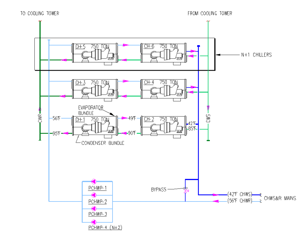
Series arrangements of chiller evaporators have been used when prudent in many ap-plications7 16 However the chilled-water plant design that was selected for this project not only arranges the evaporators in series but also arranges the condensers in series using a counterflow configuration see Figure. However the condenser pump is sized for the entire system flow in this case 2400 US GPM and this pump must operate whenever any chiller operates. The WCT 3000 chillers are suitable for series counter flow arrangement and include controls specifically designed for series chillers.
Series-Series-Series Chillers or Series-Series-Counterflow Chillers CHILLED WATER RETURN CHILLED WATER SUPPLY 55F 451F 37 F 989F 913F 85F EVEN Further Reduced lift. Compared with parallel arrangements. Water flows through the condenser in series D E F Figure 2 c.
Series Counterflow Chiller Design. 4 Chiller System Design and Control SYS-APM001-EN Primary System Components Some chiller controls can accommodate very little flow variation during machine operation2 Other more sophisticated chiller controls allow some flow variation. Flow gpm turndown 2 chiller 1 chiller system load flow one chiller min.
The heat reclaim chiller would continue to control the hot. Choose From Over 100 Types Of Hops 140. Additionally since it only utilizes straight lengths of copper it is easily cleaned and.
Centrifugal chiller will be chosen andor sized accordingly ie. Flow Chiller 1 500 1000 400 251. Water flows through an evaporator in series A B C Figure 2 b.
It may be tempting to select two centrifugal. Figure 2 6000 Ton System with Two Dual-Circuit WCT 3000 Counter Flow Chillers. The water then goes into a second chiller that cools it to 45.
That is not less than the cooling set point. Design Construction and Operation of Sustainable Buildings Arrange chillers in series counterflow to decrease chiller and system energy consumption Industry Guidance on Design ANSIASHRAEIES Standard 901-2016 Energy Standard for Buildings Except Low-Rise Residential Buildings 15F ΔT cooling coil selection 57F return1. Recognizing that the efficiency of a centrifugal chiller is sensitive to design lift in a series counter-flow plant configuration each chiller will experience different lift conditions see Fig2.
Entering-chiller water temperature. Series Chillers and VPF Chiller Plants The Three Concepts Series Chillers. For more information please refer to McQuay Application guide AG 31-003.
A two chiller series counterflow arrangement provides an associated reduction in effective compressor lift. 48F 88C 48F 88C 100F 378C 100F 378C. Impeller shroud motor etc.
Series Counterflow Chiller Arrangement Variable Primary Only. Series counterflow chillers can be 5 to 7 more efficient than a single chiller at design conditions and save up to 20 of chiller energy annually.
Consulting Specifying Engineer Series Counterflow Chiller Arrangement Benefits

Improving System Efficiency Using Series Counterflow Piping Strategy 2021 01 14 Process Cooling
The Benefits Of A Series Counterflow Chiller Arrangement Tlc Engineering Solutions

Diy Counterflow Wort Chiller

How Do I Model Series Counterflow Chillers In Trace 700

Copper Counterflow Chiller Build Home Brewing Craft Brewing Brewing Equipment

Improving System Efficiency Using Series Counterflow Piping Strategy 2021 01 14 Process Cooling

A Look At Zchiller Spiral Star Design Counterflow Wort Chiller
0 comments
Post a Comment